I thought I would kick off the blog for 2013 with what has been the most requested piece of information people have asked for...a trackplan of the layout. Below is the basic plan. Not every siding and yard track is shown. Some are but most are not.
I am not really into drawing intricate detailed plans. I like to just build as I go. At some point I will refine this plan to accurately reflect each track.And as it is, not every mainline shown is in exactly the correct position relative to the wall for fascia. It gives you a pretty good idea of how things are laid out though.
Please note that the branch up to north Stratford is not shown at all. this would be over top part of the staging, through the wall and then above Groveton and parts of Gilman. This will require a separate drawing so as not to block and confuse the drawing relative to the lower tracks below this shelf.
This plan was drawn using Empire Express software for the Macintosh, a program I have had for close to 20 years. I would suggest right-clicking on image to open it in a new tab or window, and then you should be able to zoom in. Or you could save it to your desktop and open with your favorite image viewing software (I couldn't figure out how to make blogspot show the image larger right here without diminishing the quality). Enjoy!
This web site is for information, stories, how-to's and other things relating to my model railroad, featuring the rail lines in and around St. Johnsbury, Vermont circa 1980. The model railroad features the Maine Central, Boston & Maine, Canadian Pacific and Lamoille Valley, as well as a little bit of the Central Vermont, Grand Trunk and North Stratford Railway. Feel free to comment after each posting. Also be sure to visit my main web site located at nekrailroad.com.
Wednesday, January 09, 2013
Monday, December 31, 2012
End of Year Updates
As 2012 draws to a close, I have some updates from work accomplished in December. It has been a busy month with travel and the holidays, but I have managed to find an hour here and there to get some stuff done.
First up was the trackwork in Morrisville. I soldered feeders for the frogs and dropped these to a central spot for attaching to Tam Valley Depot Frog Juicers. Next I installed the Caboose Industries sprung ground throws, which I had on hand from previous layouts and projects. I did not want these to be in the scene or for the operator to try and work their hands across yard tracks to reach them (imagine the throw at the right being reached if it was at the turnout and the yard tracks are full). So these were mounted along the front edge with music wire throw rods routed through brass tube (both from K&S). I have seen this occasionally on other layouts for hard to reach turnouts, and also on one local layout where they were all mounted along the front like this. Installs went pretty easy. Only hard part was routing tube under some track mounted directly to Homasote. In a couple spots I had to remove some plastic from the tie strip under the rail, and also make sure to insulate the brass rod to prevent a short circuit between the 2 rails (using electrical tape). But most places were easy as the track is up on foam roadbed.
The ground throws along the edge will be out of site and easy to reach. The brass tubes allow easy movement of the throw rod and will be hidden by scenery. I was asked about using under track controls, like a Blue Point or Bull Frog. First, I wanted to make use the ground throws I already had on hand. Second this spot really lended itself well to quickly and easily mounting them along the front edge. Third, I did not have much space to mount throw rod controls as I put a shelf section under this yard. The rods could probably still be fit in, but it would have been harder and more time consuming to do. So it came down to money (I already had what I needed), time (the ground throws go much quicker in this installation), and final appearance (the rod controls in this area would either not be recessed or not as easy to access for the operator).

With that complete it was on to Groveton. I completed assembly of the slide in bridge section in front of a closet which will allow the B&M track to cross from under Whitefield over to Groveton. It is wide enough to keep any derailing cars off the floor and also have a turnout here to extend the length of the passing siding and main. The bridge will simply slide into place and hit stops. I will add a piece of fascia to the front and some sort of lock to keep it from moving. Most of the time I do not need access to this closet, and never during an Op session.
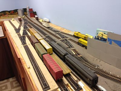
I then tried out various track arrangements to get what I was looking for. The the train will need to arrive on the main (at right) and use the passing siding to place pulled cars. When done the loco will need to run around the train to leave. There is also a
facing point turnout for woodchip unloading (car spotted there in far end of photo)
as well as the passing siding being the interchange track for cars to
and from the Grand Trunk. So a little thought ahead of time will be
needed for an operator to switch this area. Not too difficult or
unrealistic, just more to add to the fun. I removed all the track and installed the Homa-Bed roadbed. I could have used a solid piece of Homasote, but I like the idea that I can scenic the tracks as elevated better this way, plus I still have a good deal of Homa-Bed remaining to use, and no Homasote sections! So again, use what I have instead of buying something new.
I then started to lay the track, transitioning from the Code 100 hidden track to Code 83 and onto the bridge section. I used PC Board ties so I could run the rails right to the edges and keep them as secure as possible. Again, the bridge is not supposed to be moved around too often, but I wanted to make it as easy as possible with no special connector rails. I will need a single plug to power the rails on to shelf section though.
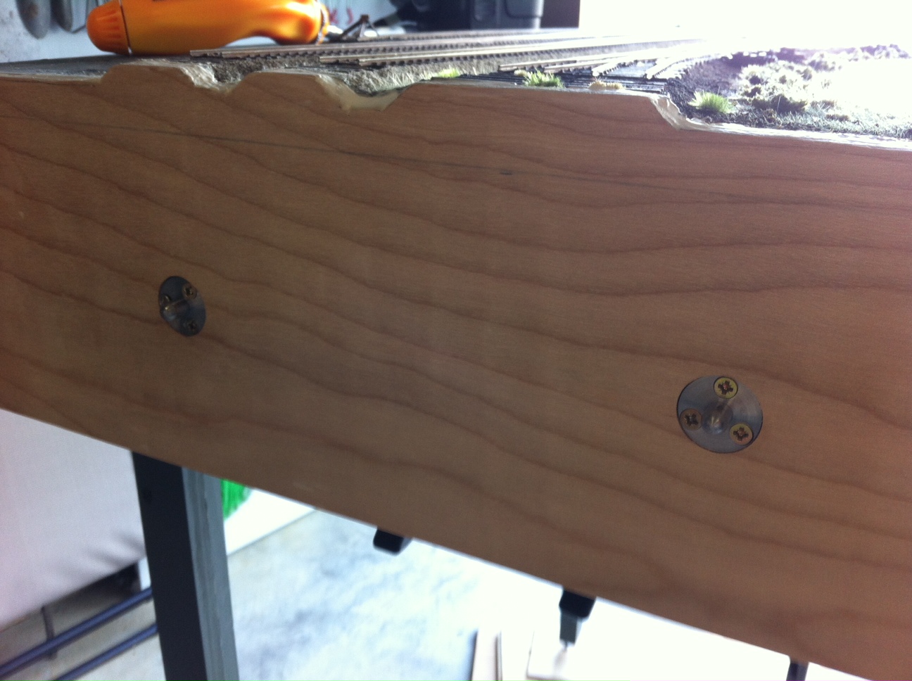
For the PC Boards, I installed flat drywall screws and filed the tops clean to accept solder. I ran the track right across the joint and then marked which ties needed to be removed, and then used latex caulk to lay the track. When dry I soldered the rails to the PC boards. I made up guard rails and soldered these in as well. When all done, I used a cut off disc in a Dremel tool to cut the rail. The result is rails that align perfectly.
First up was the trackwork in Morrisville. I soldered feeders for the frogs and dropped these to a central spot for attaching to Tam Valley Depot Frog Juicers. Next I installed the Caboose Industries sprung ground throws, which I had on hand from previous layouts and projects. I did not want these to be in the scene or for the operator to try and work their hands across yard tracks to reach them (imagine the throw at the right being reached if it was at the turnout and the yard tracks are full). So these were mounted along the front edge with music wire throw rods routed through brass tube (both from K&S). I have seen this occasionally on other layouts for hard to reach turnouts, and also on one local layout where they were all mounted along the front like this. Installs went pretty easy. Only hard part was routing tube under some track mounted directly to Homasote. In a couple spots I had to remove some plastic from the tie strip under the rail, and also make sure to insulate the brass rod to prevent a short circuit between the 2 rails (using electrical tape). But most places were easy as the track is up on foam roadbed.![]() |
The ground throws along the edge will be out of site and easy to reach. The brass tubes allow easy movement of the throw rod and will be hidden by scenery. I was asked about using under track controls, like a Blue Point or Bull Frog. First, I wanted to make use the ground throws I already had on hand. Second this spot really lended itself well to quickly and easily mounting them along the front edge. Third, I did not have much space to mount throw rod controls as I put a shelf section under this yard. The rods could probably still be fit in, but it would have been harder and more time consuming to do. So it came down to money (I already had what I needed), time (the ground throws go much quicker in this installation), and final appearance (the rod controls in this area would either not be recessed or not as easy to access for the operator).
![]() |
| Shelf under yard would have made it harder to install throw rod controls, and if recessed would have been harder to reach and operate. |

With that complete it was on to Groveton. I completed assembly of the slide in bridge section in front of a closet which will allow the B&M track to cross from under Whitefield over to Groveton. It is wide enough to keep any derailing cars off the floor and also have a turnout here to extend the length of the passing siding and main. The bridge will simply slide into place and hit stops. I will add a piece of fascia to the front and some sort of lock to keep it from moving. Most of the time I do not need access to this closet, and never during an Op session.
I then tried out various track arrangements to get what I was looking for. The the train will need to arrive on the main (at right) and use the passing siding to place pulled cars. When done the loco will need to run around the train to leave. There is also a
facing point turnout for woodchip unloading (car spotted there in far end of photo)
as well as the passing siding being the interchange track for cars to
and from the Grand Trunk. So a little thought ahead of time will be
needed for an operator to switch this area. Not too difficult or
unrealistic, just more to add to the fun. I removed all the track and installed the Homa-Bed roadbed. I could have used a solid piece of Homasote, but I like the idea that I can scenic the tracks as elevated better this way, plus I still have a good deal of Homa-Bed remaining to use, and no Homasote sections! So again, use what I have instead of buying something new.I then started to lay the track, transitioning from the Code 100 hidden track to Code 83 and onto the bridge section. I used PC Board ties so I could run the rails right to the edges and keep them as secure as possible. Again, the bridge is not supposed to be moved around too often, but I wanted to make it as easy as possible with no special connector rails. I will need a single plug to power the rails on to shelf section though.
For the PC Boards, I installed flat drywall screws and filed the tops clean to accept solder. I ran the track right across the joint and then marked which ties needed to be removed, and then used latex caulk to lay the track. When dry I soldered the rails to the PC boards. I made up guard rails and soldered these in as well. When all done, I used a cut off disc in a Dremel tool to cut the rail. The result is rails that align perfectly.
![]() |
| Screws ready for PC Board to be soldered in place. |
![]() |
| PC Boards installed, and gaps cut in copper to prevent short circuits between rails. |
![]() |
| Track laid across joints with adhesive caulk and pinned in place. |
![]() |
| Main rails and guard rails soldered in place, and rails cut. |
Now it is on to the rest of the tracklaying in Groveton. I have enough track and all the turnouts, so this should continue to move along. Once the track is done, and wired, and the ground throws installed (I think this area also lends itself to this type of installation), I can paint the track here and in Morrisville. But I don't plan to do anymore scenery than that. I want to continue to focus on installing the rest of the track, so it will be on to Whitefield to connect the B&M to the diamond with the Maine Central, as well as installing the couple of sidings there.
I can then move onto the last local areas needing trackwork (besides the mainlines which are in place), Johnson, Sheldon Jct., Lyndonville, and North Stratford. But I do not have to get these done before holding an informal Ops Session, one to just get people acquainted with the layout and run a portion of the train schedule. My goal last summer was to do that during this winter, and with Morrisville and Groveton in place, I think that is feasible. So the goal will be sometime in February or March to do that. Here's hoping I can keep that New Year's Resolution!
Monday, December 03, 2012
Open House Pictures
The layout was opened for two days in November and I had about 80 total people come through, less than last year (when a newspaper article covered the open house), but still a good number with some new people and some regulars. As usual I always forget to take pictures while people are visiting. I just get busy talking to people while also keeping an eye on the running trains. But with the layout all cleaned up I did take some pictures after the last visitor left. For those that could not make it this year, these pictures will help convey the current state of building progress.
![]() |
| A look at the farm scene and Fisher Bridge along the LVRC. I tried a new angle here, so it should look familiar but somewhat different than previous pictures I have posted. |
Saturday, November 24, 2012
Photos from NEFF RPM
I had a good time attending the Northeastern Fallen Flags Meet back in September. The event in Bridgewater, NJ occurs annually, and I hope to attend again in the future. I got to see a lot of great models and talk to lots of great people, some I knew and others for the first time.
I presented my clinic on Free-mo modular railroading and had my module set up in one corner of the large gym building. I did not get to attend any other clinics this time as I was busy talking to people and operating the module most of the day. Thanks to Geert Marien for helping man the module so I could get away for my clinic and to look at some of the great models on display. Here are some of my pictures.
The date for next years event has not been set yet. Check the web site below for more info on the event as well as additional pictures.
http://www.hansmanns.org/neff_rpm/
I presented my clinic on Free-mo modular railroading and had my module set up in one corner of the large gym building. I did not get to attend any other clinics this time as I was busy talking to people and operating the module most of the day. Thanks to Geert Marien for helping man the module so I could get away for my clinic and to look at some of the great models on display. Here are some of my pictures.
![]() |
| My Woodstown Jct. module set up and operating for the day's event. |
![]() |
| Geert Marien operates a train while some young model railroaders look on. |
![]() |
| Lenny Harlos from Thoroughbred Models tests out one of his sound equipped custom weathered locomotives on the my module. |
http://www.hansmanns.org/neff_rpm/
Monday, October 29, 2012
October Timonium Pictures
Another fun time down at the train show in Timonium, MD, with the guys from Capitol Free-mo. I arrived early Saturday morni ng and most of the layout was already set up from Friday night. An obvious gap in the layout indicated where I needed to put my modules. By 9am we had trains rolling on what I think might be the largest Free-mo layout we have assembled as a group. Here is a picture of my module fully set up within the layout. You can see the new interchange shelf I built in the foreground. I also have a clamp on shelf, which is actually left over L-girder benchwork! I plan to make a proper and painted clamp on shelf before the next show. It comes in real handy.
Even though I bring a stool, my legs get mighty tired after two days of this show. As you can see the layout goes on a ways. in the distance is the Steel Mill modules of Jim Musser, as well as some interesting curved sections. Way off but unseen is a staging module Jim built just for this show. This made operations possible and we did run some car card and waybill ops on Saturday. The next picture is a reverse look at my modules. There is only one long module on the layout after mine, beyond the truss bridge, Boston Street, which will feature car ferry operations.Up front on the left you can see my in progress corn syrup plant. Once completed, this first section of the module set will be complete, minus a few more scenery details which can always be added.
I used a piece of styrene to represent a parking lot that helps conceal the gap between section 1 and section 2. Here you can see the basic piece with a little weathering. I need to add a guard rail, parking stops, and lines to finish it off, but it does a good job so far. The ice machine is from Nick & Nora, a neat little detail item. The 7up machine is just a photo printed and glued to a styrene block.The GP40-2W is by Atlas which I weathered. One of the reasons I decided to build the modules is so I could run some newer equipment like this that does not fit on the layout (circa 1980).
Speaking of hiding module joints, before the NEFF show, I took time to rebuild the ends that mate between sections 1 and 2 and also put in alignment pins from C&L Finescale. this helped get a better flush finish so I could run the scenery to edge better, and also allows for easier set up and alignment. With that done I want to work on securing my rail ends to PC tie boards and run them to the end to eliminate the fitter rails. Heer is is a look at the new ends.
One other interesting note from the Timonium show. One member is on a work assignment in Afghanistan but was able to construct a module there using available materials and some shipped in scenery and track. He boxed up the module to send back home and when he got back he brought it to the show. Just goes to show you that if there is a will to do some model railroading, there is a way!
I took video of the layout from my iCar and you can check that out on YouTube:
Capitol Free-mo Layout, October 2012 - http://bit.ly/Ricq1w
![]() |
| Woodstown Junction in the Capitol Free-mo layout. |
I used a piece of styrene to represent a parking lot that helps conceal the gap between section 1 and section 2. Here you can see the basic piece with a little weathering. I need to add a guard rail, parking stops, and lines to finish it off, but it does a good job so far. The ice machine is from Nick & Nora, a neat little detail item. The 7up machine is just a photo printed and glued to a styrene block.The GP40-2W is by Atlas which I weathered. One of the reasons I decided to build the modules is so I could run some newer equipment like this that does not fit on the layout (circa 1980).
Speaking of hiding module joints, before the NEFF show, I took time to rebuild the ends that mate between sections 1 and 2 and also put in alignment pins from C&L Finescale. this helped get a better flush finish so I could run the scenery to edge better, and also allows for easier set up and alignment. With that done I want to work on securing my rail ends to PC tie boards and run them to the end to eliminate the fitter rails. Heer is is a look at the new ends.
| New birch plywood added to the end and alignment pin hardware installed. |
| This is the hardware I used, ordered from England. |
I took video of the layout from my iCar and you can check that out on YouTube:
Capitol Free-mo Layout, October 2012 - http://bit.ly/Ricq1w
Tuesday, September 25, 2012
Free-mo at NE Fallen Flags RPM, Bridgewater, NJ
This weekend I will be up in Bridgewater, NJ for the annual Northeastern Fallen Flags Prototype Modelers Meet. It is Saturday, September 29th from 9am to 6pm. Check out the web site below for more info.
http://www.hansmanns.org/neff_rpm/index.htm
This will be my first time attending this event. I was asked to bring my Free-mo module and also give my Intro to Free-mo clinic.Hope to see you there!
http://www.hansmanns.org/neff_rpm/index.htm
This will be my first time attending this event. I was asked to bring my Free-mo module and also give my Intro to Free-mo clinic.Hope to see you there!
Monday, September 10, 2012
November Open House Dates
The annual model railroad month open layout tour throughout NJ, PA, DE and MD is in final preparations. this year my layout will be open on Sunday, November 4th and Saturday, November 10th, both days 12 noon to 5pm.
More layouts, including ones you can visit nearby me on the same days, are always listed on www.modelrailroadopenhouse.com
I hope you will be able to stop by and say hello!
More layouts, including ones you can visit nearby me on the same days, are always listed on www.modelrailroadopenhouse.com
I hope you will be able to stop by and say hello!
![]() |
| Fall is in the air - must be Model Railroad Month! |
Friday, August 31, 2012
End of Summer updates
As you can tell by the inactivity here on the blog, there is not too much to report on the model railroading front during the summer months. At the end of May, I finished up the fascia work, including staining and applying the clear finish, to all remaining areas of the layout. This certainly now gives the layout and the room a real finished look throughout.
Now on to getting some track down in Groveton and North Stratford!
I also completed a couple of LVRC RS3s for some customers, including one that was chop nosed. Just recently, Atlas announced a new run of RS3s and they will be doing 2 road numbers of the Lamoille Valley. I knew this would happen eventually as just about every small railroad has been getting included in new releases by manufacturers. So there may not be any further demand for custom painted LVRC RS3s, but having done about 2 dozen of them, I am OK with that! As these locos are difficult to get sound into, I might be looking at replacing one of mine with a sound equipped Atlas offering.
In June it was reported here locally that a large model railroad would be coming down as the owner was going to move. I used my iCar to do a a bit of video work covering many areas of the layout before it was gone. These have been edited down and posted to YouTube. Here are some links:
Video 1 - Bayview to Clairmont
Video 2 - Clairmont to Sayre
Video 3 - Tamaqua to Easton
I still have a couple more to post, but the good news is that the layout will remain as the owner changed his plans for moving. So we still have more Op Sessions to look forward to on this large layout in the future.
In early July I did get a little time to finish up feeder wiring for the yard in Morrisville. All track tested and functional, although I do need to install ground throws for the turnouts.
I also finally fixed a pesky issue with a Maine Central U18B (Intermountain with QSI sound). Loco was totally unresponsive and made no sounds at all, and could not be accessed from a boosted programming track. I could tell power was making it to the board with a tester, so I figured maybe the chip was fried or something. I called QSI for suggestions but they could not help as the decoder was factory installed. I decided to pull out the chip out of the decoder board socket and swap it with a working one from another unit to see if it resolved the issue. Then I worried that I might end up with 2 bad locomotives. So I put the same chip back in and tried one more time. Finally the loco responded! I have no idea why pulling the chip and putting it back in would have any effect, but it did. So something to remember for the future should this happen again. In general, I have not been a big fan of the QSI decoders because of weird things like this (and function key magic that sometimes allows the sound to work but the engine to not move). They do sound good in the U18Bs though.
In August, about all I accomplished was measuring and cutting wood for a drop in section that will connect Groveton to the rest of the layout in front of the bi-fold doors. I did not get to assembling this bridge section yet, but all pieces are cut and waiting for me.
Summer is now coming to a close and I look forward to getting some more time to spend on the layout as well as the modules (as there are some events coming up for Free-mo).
![]() |
| View down main aisle, new stained fascia in Whitefield on left, and Groveton, N. Startford (upper) and Gilman in back. |
![]() |
| Groveton on left, N. Stratford (upper), Gilman (back right) and Lyndonville (right). |
I also completed a couple of LVRC RS3s for some customers, including one that was chop nosed. Just recently, Atlas announced a new run of RS3s and they will be doing 2 road numbers of the Lamoille Valley. I knew this would happen eventually as just about every small railroad has been getting included in new releases by manufacturers. So there may not be any further demand for custom painted LVRC RS3s, but having done about 2 dozen of them, I am OK with that! As these locos are difficult to get sound into, I might be looking at replacing one of mine with a sound equipped Atlas offering.
![]() |
| LVRC 7803 with chopped nose ready to ship to a customer |
In June it was reported here locally that a large model railroad would be coming down as the owner was going to move. I used my iCar to do a a bit of video work covering many areas of the layout before it was gone. These have been edited down and posted to YouTube. Here are some links:
Video 1 - Bayview to Clairmont
Video 2 - Clairmont to Sayre
Video 3 - Tamaqua to Easton
I still have a couple more to post, but the good news is that the layout will remain as the owner changed his plans for moving. So we still have more Op Sessions to look forward to on this large layout in the future.
In early July I did get a little time to finish up feeder wiring for the yard in Morrisville. All track tested and functional, although I do need to install ground throws for the turnouts.
![]() |
| Not much to look at, but the wiring needs to be there for reliable operations! |
I also finally fixed a pesky issue with a Maine Central U18B (Intermountain with QSI sound). Loco was totally unresponsive and made no sounds at all, and could not be accessed from a boosted programming track. I could tell power was making it to the board with a tester, so I figured maybe the chip was fried or something. I called QSI for suggestions but they could not help as the decoder was factory installed. I decided to pull out the chip out of the decoder board socket and swap it with a working one from another unit to see if it resolved the issue. Then I worried that I might end up with 2 bad locomotives. So I put the same chip back in and tried one more time. Finally the loco responded! I have no idea why pulling the chip and putting it back in would have any effect, but it did. So something to remember for the future should this happen again. In general, I have not been a big fan of the QSI decoders because of weird things like this (and function key magic that sometimes allows the sound to work but the engine to not move). They do sound good in the U18Bs though.
In August, about all I accomplished was measuring and cutting wood for a drop in section that will connect Groveton to the rest of the layout in front of the bi-fold doors. I did not get to assembling this bridge section yet, but all pieces are cut and waiting for me.
Summer is now coming to a close and I look forward to getting some more time to spend on the layout as well as the modules (as there are some events coming up for Free-mo).
Wednesday, May 23, 2012
Paper Buildings
You may have noticed a recent increase in the use of and articles about using paper based materials for structures on model railroads. Lance Mindheim has written about using prototype photos for the basis of structures on his relatively modern layout in multiple publications (www.lancemindheim.com). And there are a number of good examples of roofing and siding material printed on sheets of thicker paper by companies such as Kingmill, Clever, Paper Creek (out of business now) and others that you can find on-line, at your hobby shop and at train shows.
Recently while reading the ongoing saga of nearby modeler Rick Bickmore's steel mill themed layout over on the 'railroad-line' forum, Rick mentioned a British company offering some interesting paper based structures that he has been using for buildings on his layout. (check out Rick's discussion at http://railroad-line.com/forum/topic.asp?TOPIC_ID=20007&whichpage=104. Page 104 is right in the middle of the paper model discussion and has nice photos of Rick's 84 Lumber building. If you have some time, the other 100 or so pages that detail Rick's layout and model building are a pretty good read with lots of tips and ideas).
The company Rick mentioned was Scale Scenes, http://www.scalescenes.com/. They have a free download to try of a low relief brick building that would work well against the backdrop. The free download link is right off the main page.
What you get is a of PDF file that you print yourself. They have 2 different brick colors to choose from and a separate PDF download for the instructions. The instructions are great and I had no problem following along and building the model. The structure PDF itself I printed on a color printer. You need to resize the output to 87% to get true HO (they have instructions for printing to other scales as well). This was no problem at all. I also sprayed the output pages with Krylon Matte Finish to protect the ink and prevent it from damage during assembly.
The process involves gluing some of the sheets to thicker paper, such as matte board (Heavy Card), Poster Board (Medium Card) and 67lb paper (Light Card) to give you stronger sections and allow for gluing surfaces of walls ends. The web site has some details in the FAQ that can answer questions on what paper and card to use. Some of the sections are wrapped with another image and help build out the 3 dimensional details of the building. the door and window pieces are glued with clear styrene in between for window glazing. I used Canopy Formula 560 glue and that worked real well on this structure along with a glue stick for gluing larger sheet sections to their backers. Overall I found the kit to be really well thought out and convincing.
Here are pictures of the completed structure. Considering it cost me virtually nothing to build this, I am pretty happy. I like how it includes the 3 dimensional aspects such as the end pieces and roof caps, as well as the recessed window and interior office. There is just enough there to fool the eye. Some additional features, like down spouts and lights would also help.
| Basic completed structure. I have not added any weathering to this at all, and may not need to. |
| The interior office adds a lot of dimension, and I look forward to adding some people, a vehicle and other detail parts. |
I will probably investing a few "euros" and purchase one of their other kits. Rick discusses how he just used multiple print outs from one kit to give him plenty of siding material for the "paper-bash" of his 84 Lumber kit. I agree this is great idea and can really help get some structures on the layout, whether they are permanent or just mock ups.
Sunday, May 20, 2012
Final benchwork and trackwork progress
As we head towards summer, I am still trying to stay busy working on the layout and associated projects. Recent news about a nearby layout being taken down, and the subsequent end to a monthly operating session there really have me wanting to keep work progressing towards getting my layout ready for an operating session. In that regard, I have made more progress, getting subroadbed and fascia in place for the Groveton paper mill area. This represents the last area of relatively major "lumber cutting". With this in place, I can finalize plans for trackwork here and put in the removeable bridge that the B&M will use to cross in from of the utility closet between Whitefield and Groveton.
Along with this work, I did more of the fascia work and under shelf construction for Gilman and Lyndonville. These are nearly complete and I will post pictures of that once they are completed. At that point I will be able to stain and clear coat the rest of the fascia, moving the overall layout area to a completed look. it also will help the operators as I will be able to give them a place to work with the waybills.
The other major area needing attention was the yard and industry tracks at Morrisville. Operating the LVRC really would not be possible without this in place, and I am happy to report that all track is in place. I still need to install ground throws, but it is possible to operate without them as I have seen on other layouts.
![]() |
| Morrisville finally has yard tracks and industry spots to switch, plus tracks to head into the engine house. |
Trackwork still remains to be done for the B&M in Whitefield, specifically a couple of spurs past the ball signal that will add operational interest. This is not needed however before an operating session commences, This can be added later, with appropriate waybills cycled in at that time too.
Another similar area to get trackwork is the talc mill on the LVRC at Johnson. This will be an industry that will ship and receive a fair amount of covered hoppers, but again does not need to be in place before the first attempted operating session. The area here has received no attention since the initial benchwork went in place 6 years ago. I don't even have a picture of the area!
The industrial park at Lyndonville has long been my "last to do" area because of the convenience of having a large flat area to work on things (see first photo, lower right). I could think about simply running some flex track here and having the local just drop the cars there while I contemplate where to spot the industries I have planned, and that I have already made up waybills for!
A final small location needing some additional trackwork is the CV interchange with the LVRC at Sheldon Junction. I anticipate one or two CV served industries here, but right now there is just a switch off the CV main. Also another example of something that can wait, or can at least be temporarily set in pace with flex track and some spikes. Initially the CV trains do not even have to be operated as they are not critical to any other trains on the schedule.
![]() |
| This area has not changed at all since I took this picture a few years ago. Those CV engines need an industry or two to switch, don't you think? |
The point seems to be that I could indeed probably look at the calendar now and set a date for an initial op session. Something to get a crew familiar with my layout and concept, and run a subset of the overall train schedule. The Maine Central is fully in place. The CP could also be operated with at least that temporary track in Lyndonville to receive the local cars. The B&M does not need to be fully functional at this time, and could perhaps just terminate at Groveton on a temporary track after it works the Whitefield interchange. The LVRC can also be fully run, perhaps leaving the covered hoppers for Johnson in the yard for now (replacing empties also in the yard).
I can think of a ton of other things I would like to do before an initial session, but I wonder if it is just better to plan on a date and do it. Otherwise it seems I will always be pushing it back as I find more things to work on that seem "critical" but probably are not when a layout is first starting to get operated.
Monday, April 02, 2012
Whitefield Ball Signal
One of the signature scenes on the Maine Central's Mountain Subdivision is the ball signal protecting the crossing with the Boston & Maine in Whitefield, NH. Even in 1980, the time period of my layout, train crews would stop here and raise or lower the ball signals to get authority to cross the diamond.
On my layout I have included this scene and have had the Best Trains kit of the signal and supporting structures ready to be built for some time. Recently, my wife was interested in working on another structure as she has done in the past and I pulled this kit out. She worked on the signal shanty and car shed while I assembled the ball signal. I used some craft beads for the ball signals instead of the ones supplied in the kit as they represent an older style which was replaced in the 1970s.
Once we had the shanty and signal complete (although the shanty is still without the faded tar paper roof like the prototype shot above), I could not resist mocking up the scene on this unscenicked area of the layout. I posed a MEC and B&M locomotive here and recorded the grand moment.

Friday, March 30, 2012
Cat-proofing the LVRC
My Lamoille Valley track runs around the walls from St. Johnsbury to Johnson before passing through the wall into a small closet area, then reentering the layout room below these scenes on the wall to get to Sheldon Junction and the Central Vermont. As the picture shows, this hidden track is just a simple piece of wood to span between the wall holes.
Well, I have found that my 2 relatively new cats have figured out how to open the bi-fold doors which can lead into this area. Being curious they seemed to have learned that this shelf leads to holes in the wall and ultimately a whole new place to explore. As I found out one day when the remnants of what I can only guess was Hurricane Lexie followed by tropical Storm Roxy...broken trees, freight cars knocked on their sides, some power lines down in Hardwick...even the moose at Fisher Bridge was "sleeping" in the water.
To avoid a repeat of this, I installed a simple foam core protective cover for this track and used sections on top secured by blue painters tape to act as hinges, meaning I can lift up the top and get to the track for maintenance.(I have a pretty good supply of foam core board from a friend)
I am happy to report no further feline incursions to the Northeast Kingdom!
| Before, pretty easy access for the cats to the layout room through those holes |
| With the protection in place, the cats can only visit the layout room under supervision! |
| Were we bad? |
Tuesday, March 20, 2012
An update on Car Cards and Waybills
Between other modeling projects I have slowly been
finalizing my car cards and waybills. As mentioned before, I was intrigued by
the more prototypical waybill and especially the plastic sleeve mentioned in
Model Railroader’s Feb. 2012 issue. I did order some plastic sleeves and these
worked well with the car cards I already had once I trimmed off the fold up
pocket.
Next I turned to the waybill. Using the template provided in
Excel on the MR web site, I started adjusting boxes in the document and
removing things I did not like. The result was a 2” x 2-1/2” area to identify
the shipper, receiver, their locations, the commodity and any special
instructions. It follows the basic left-right concept of the prototype template,
but eliminates a few things to allow larger printing of the data that mattered.
I found that I could group 4 waybills in a block and by folding them I could
get all 4 steps, one at a time, to be displayable on the front, simply by
turning the waybill front to back, then folding it and doing the same again.
Kind of hard to describe but the pictures below should help. Once cut out and
folded, it was inserted into the plastic sleeve, overlaying the car card.
I printed these on white paper but used Blue print for the
variable data and highlighted the box representing the destination location as
this is usually what an operator is most interested in knowing. After doing a
few of these, I was satisfied that this would work, so I went ahead and ordered
enough plastic sleeves (vinyl actually) for the rest of my rolling stock and
set forward on the task of creating waybills.
In excel I created new sheets for different cars and
routings and printed these out, matching them up with likely freight cars. For
example paper will move in MEC boxcars, appliances
will move in my D&RGW HyCube boxcar, etc. This takes time, and can really
get to you, so it is best to do a little at a time I find. So far I have done a
little more than half of all my rolling stock. I have been keeping track of how
many waybills I create for each siding and staging track as recommended in the
article I referred you to in the last post.
One thing it quickly identifies is where I have a need for
certain freight cars, and maybe too many of another. For example, I doubt I
need any more boxcars (although it will be tough not pick up new ones that come
out) but I have no oil tank cars that I need for the MEC to interchange with
the B&M at Whitefield for the paper mill to the north. So this will help me
focus a bit on cars I should be looking for in the future.
Here are some pictures. The first shows the waybill printed
and cut out. You can se the fold lines. Also note that I used a highlighter in
the boxes for step 3 and step 4.This was something that I picked up operating
on someone elses layout. The color coding can help yard operators quickly identify
how to route cars. An orange highlight is for cars heading on the MEC to
Portland. A Green highlight is for cars heading up north on the CP. I also have
blue for southbound cars on the CP/BM and Yellow for cars destined for the CV
St. Albans yard. This can help an operator who may not be sure how a car should
be forwarded.
Next is a picture showing all phases of the car card and
waybill. You can see the plastic sleeve, the sleeve with car card and finally
also with a waybill. Above that is the waybill before and after folding.
Finally here is a look at the completed product for a number
of different car types on the layout. I color coded the car cards to help crews
identify them .
| The car cards in their plastic sleeves with waybills inserted. |
So far I am pretty happy to have found a way to address this
need to move me closer to operations. I know once we start I will probably need
to tweek the waybills, and possibly fix some errors. But this has me on a good
start. Now, to finish waybills for the remaining cars…oh yeah, and I need to
print some car cards for the freight cars I picked up at Springfield in January…
Subscribe to:
Posts (Atom)


.jpg)